Inner Tank
DESCRIPTION:
The INNER tank is attached to the floor of the OUTER tank with ten (10) screws driven into blocks in the base of the OUTER tank. These strengthening blocks help to support the weight of the water (about 6+Kg). This INNER tank is not really a "tank" because it is open at both ends. It is a cylinder with wide slots at the top to allow water to flow down into the "tank" from the top.
The INNER Tank is supported by ten (10) radial vertical blocks that support the miniature electric motor driven propellers. These blocks are attached to the floor of the OUTER tank with a round connecting plate. The following images show the two sections, both separate and connected together. The INNER Tank, the support columns and the connection plate are all fused together and 3D printed as one piece.
DIMENSIONS:
This INNER Tank has a diameter of 200mm, a height of 217mm, and a wall thickness of 3mm. It is supported by a six (6) vertical columns. There is one (1) central vertical column and five (5) outer radially equally spaced columns, each 72° apart. The vertical columns have a height of 128mm with an overlap with the INNER Tank of 11mm. There are five (5) miniature electric motors/propellers mounted on the top of these vertical columns.
FEATURES:
(1) The five (5) miniature electric motors/propellers mounted on the top of these vertical columns create a flow of water downwards that causes floating items on the surface to be drawn down and retained in the collection net.
(2) Below the propellers are five (5) fixed "rudders" that are angled vertically outwards at an angle of 45°. These direct the flow of water outwards after surface debris is collected.
NOTE: In the 1:30 scale model, these "rudders" rotate and provide the OGG Pods with directional and rotational abilities.
SCREW HOLES:
(1) There are ten (10) Screw holes of 3.6mm diameter, all evenly spaced on a circle of 217mm, each 36° apart. These screw holes are positioned on the circular connection plate which attaches the INNER Tank to the base of the OUTER Tank. The diameter of the connection plate is 231mm.
(2) There are also two (2) additional levels of blocks that are attached to the sides of the INNER Tank. There are ten (10) of these blocks, five (5) on each level. They each require screw holes of 3.2mm, radially spaced on a circle of 184.3mm, each 72° apart. The UPPER blocks support the collection net ring at the top while the LOWER blocks support the collection net at the bottom.


PLAN VIEW
INNER TANK
SIDE VIEW


STEP 1:
As per the diagrams below, add the central vertical column and the five (5) radial vertical columns to the base connector disc. Each Column has 4 screw holes of 3.2mm diameter (2 lots of 2), making a total of twenty (20) screw holes. Self-tapping screws (3.4mm diameter) are screwed into these holes to secure the miniature electric motors/propellers into their correct position. The red outlined rectangles in the PLAN VIEW, show the critical dimensions and positions of the screw holes. These screw holes must match the mounting plates of the motors exactly. The base connector disc has ten (10) screw holes of 3.6mm diameter, so the self-tapping screws pass through the screw holes and screw into the floor of the OUTER tank. These six (6) vertical columns are 3D printed together at the same time with no separation, so they ALL become one piece.


STEP 2:
As per the diagrams below, add the five (5) fixed "rudders". Start with the radial vertical rudder support struts. These connect to the central vertical column support at the top and to the base connection disc at the bottom. These support struts hold the fixed rudders in place at an angle of 45°. The rudders themselves connect with BOTH the central vertical support column AND each outer radial vertical support column. These positions are highlighted with red circle outlines. These rudders then direct the flow of water from the propellers outwards. The rudders and their support struts combine with the base connection plate and the vertical column supports when they are 3D printed, forming one single piece.


STEP 3
As per the diagrams below, add the INNER Tank to the structures created in the two (2) steps above.
This INNER Tank overlaps the vertical support columns by 11mm, to add strength to the overall structure.
Note the five (5) positions where the INNER Tank wall fuses with the five (5) OUTER vertical radial support columns. These positions are highlighted with red circle outlines.


STEP 3 (cont'd)
With the basic INNER Tank structure completed, we can now place the miniature electric motor/propellers in their operational position. We can also now show the outer vertical radial support columns FUSED with the INNER Tank wall. The fused positions are highlighted with red outlined circles in the PLAN VIEW only.
There are still two (2) remaining steps that are required to position, support and protect the collection nets.


STEP 4
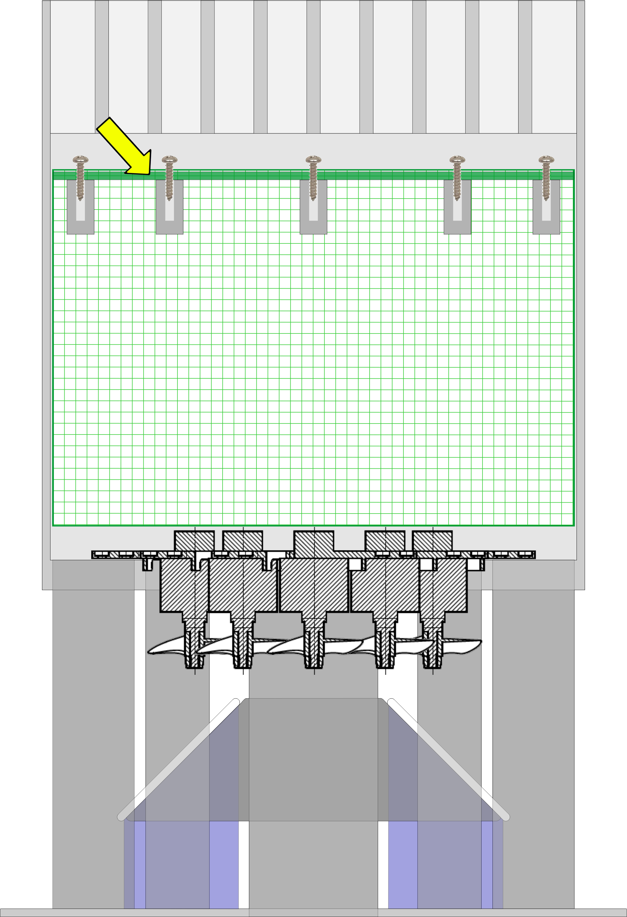
We now need to place the debris collection net into a secure operational position. Beginning at the circular positioning ring at the top of the net. This ring sets the net position at the correct level below the surface of the water and holds the net securely in place. This ring is 1-2mm smaller than the internal diameter of the INNER Tank. This allows for secure positioning of the net material OUTSIDE the ring, firmly between the ring and the INNER Tank wall. This net positioning ring is secured to five (5) radially positioned vertical blocks with screws. Each block is 10.5mm wide with a 3.2mm diameter screw hole to enable the retaining ring to be securely fastened to the INNER Tank wall. The retaining ring is shown here in green and a yellow arrow highlights the position of the ring in the SIDE VIEW.


We have now created a secure position for the collection net, so we can now show it in position.
Single Collection Net and Ring Position

Multiple Collection Net and Ring Positions


STEP 5
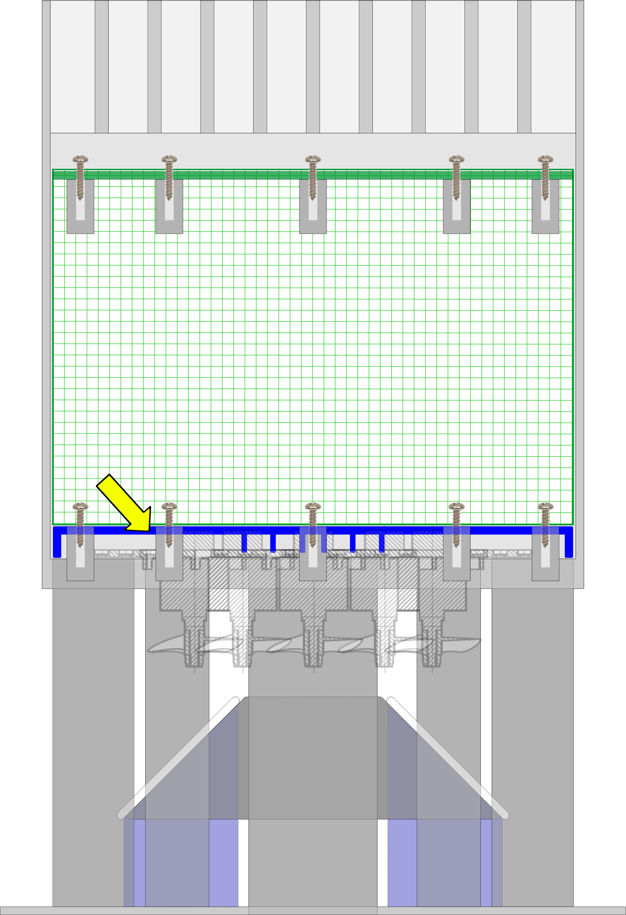
Now that the debris collection net has been located in a secure operational position, we can now add the lower support ring for the collection net. This support ring acts as a barrier to ensure that the collection net is not drawn downwards and into the path of the propellers. As shown in the SIDE VIEW diagram below, the horizontal positioning of the lower support ring is exactly the same as the collection net ring of STEP 4 except that it is in a lower vertical position.

STEP 5 (cont'd)
The net support ring also has central raised circular sections and outer perimeter raised sections that keep this support ring away from the propeller electric motors. These raised sections are shown in red in the PLAN VIEW Diagram. The SIDE VIEW shows the expected water level surrounding the INNER Tank.


More Reference Diagrams:


